

Introduction
Perforator flaps are widely used throughout reconstructive surgery. From pedicled ‘free-style’ perforator flaps in lower limb reconstruction, to free perforator flaps in breast reconstruction, the micro-dissection of perforators as the basis for flap vascularisation is routinely performed. An understanding of flap perfusion is essential and imaging techniques continue to evolve in order to better demonstrate this anatomy. Early imaging techniques in perforator flap surgery only focused on identifying the location and calibre of perforators, however, greater sophistication in both imaging and flap design has led to a clinical need to map the perfusion zones of individual perforators thus, facilitating favourable surgical outcomes in flap reconstruction.
The perforasome concept describes the vascular territory supplied by a single arterial perforator and is an evolution of the angiosome concept described and imaged in 1987 by Taylor and Palmer.1 Since those initial descriptions of the perforasomes by Saint-Cyr and colleagues2 and Rozen and colleagues3 nearly a decade ago, several studies have employed various methods to explore and describe these territories, with varying efficacy.
The current paper comprises a review of the evolving techniques for mapping perforator territories, used in varying capacities as a means to successful perforator flap design, reduction of fat necrosis and peripheral flap ischaemia. As yet, no imaging technique has been identified as the ‘ideal’ perforasome imaging method, making this an exciting time to be at the forefront of this emerging field of discovery.
Methods
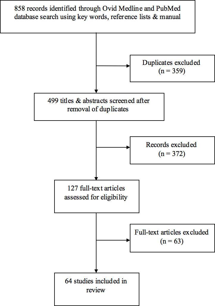
This article presents a qualitative analysis of the current literature on perforasome imaging. A literature review of PubMed and Medline was performed using a combination of the key words ‘perforasome’, ‘perforator angiosome’, ‘perforator flap’, ‘perfusion’ and ‘imaging’ and limited to English language studies of humans published in the period 1980–2017. Additional references were identified through bibliographic linkage were also considered. A total of 858 articles were identified.
Articles were excluded if they did not specifically describe or focus on a perforator or perforasome imaging technique. Studies that did not meet inclusion criteria but were relevant for historical reasons were included in the discussion but not in the formal review.
Results
After exclusions, 51 studies met criteria for inclusion in this review (Figure 1). Six imaging techniques were discussed within these studies (Table 1). To date, there is mostly level III and IV evidence for these techniques, although level II studies are emerging. There is currently no level I evidence for any imaging technique. Table 1 also categorises the study types which explore these techniques. This paper addresses established perforator imaging techniques and subsequently, their potential for application to perforasome imaging.
Perforator imaging techniques
Doppler sonography
While not strictly an imaging technique, hand-held Doppler ultrasound has long been used to locate perforators in flap planning.4 This use of sonography has significant limitations, such as both high false-positive5,6 and false-negative rates,6,7 lack of information regarding calibre, flow volume6 and perforator course,8 and operator dependence.9 However, the method is cheap, simple to use, non-invasive and risk-free for the patient and can be used in conjunction with preoperative imaging.
Colour duplex ultrasonography
Colour duplex ultrasonography holds many of the benefits of hand-held Doppler while providing more information on the flow volume, calibre and course6 of perforator vessels. Its accuracy is superior to hand-held Doppler,5,6,10 given its added ability to visualise vessels. Other studies show CDU to be inferior to CTA for identifying perforators in the abdomen,11,12 though Zhang and colleagues describe CDU as having higher accuracy than CTA in mapping of perforators in the lower extremities.13 Notably, contrast-enhanced ultrasonography plus three-dimensional reconstruction has been reported to increase accuracy and precision14 when compared with regular CDU and hand-held Doppler.
While CDU involves no radiation exposure and is negligibly invasive, it only gives two-dimensional detail, cannot display perforator branching networks and other relevant vessels12 and it is operator dependent.9 However preoperative sonography is routinely used.15
Computerised tomographic angiography
Computerised tomographic angiography is generally accepted as state-of-the-art for perforator visualisation.16,17 Its high accuracy11,18–22 and excellent image quality mapping of location, calibre, course and branching of a perforator,11,23 have led to reduced operation times and fewer postoperative complications.23,24
As the first technique to produce highly detailed perforator images,16 CTA is well-studied as a preoperative perforator visualisation technique in multiple types of perforator flaps. While CTA requires radiation exposure and an iodinated contrast injection, there are many benefits. It is affordable, accessible and operator-independent, gives significant detail on perforator anatomy and can visualise small vessels to 0.3mm in diameter.25 Additionally, CTA has better fat-to-vessel contrast than MRA, allowing easier mapping of a perforator’s subcutaneous course, though intramuscular course is clearer on MRA.26,27
Another feature of CTA is its potential for three-dimensional image processing,28 such as volume rendering reconstruction,17 which can facilitate interpretation of scans and provide visual representations of perforator location and course.
Given CTA’s main and significant disadvantage is its use of contrast and radiation,23,24,26 there has been investigation into using lower doses of both.29 Several studies have found that low-dose techniques achieve high-quality vascular imaging similar to conventional CTA.29,30
Overall, CTA is an excellent resource for preoperative perforator imaging with continuing developments to mitigate the risks of iodinated-contrast and radiation exposure.
Magnetic resonance angiography
Magnetic resonance angiography provides a three-dimensional image of perforator vessels but often using safer, non-iodinated contrast-enhancement. There are several contrast agents that provide varying levels of resolution. With the development of blood-pool contrast agents such as Gadofosveset (also known as AblavarTM or VasovistTM), MRA can clearly depict perforator intermuscular course due to its superior muscle-to-vessel contrast ratio.26,27 Kagen and colleagues31 reported that MRA produces a high-resolution image with similar spatial resolution to that of CTA.
Newman and colleagues found high sensitivity and specificity of MRA in identifying perforators,32 and a review by Saint-Cyr and colleagues showed that MRA and CTA were essentially equal in preoperative location of perforators.33 Another paper by the same group also illustrated that MRA has high concordance with intraoperative findings and decreases partial flap failure rates.34
Equilibrium-phase MRA is reported to be superior to first-pass MRA at visualising perforators.35,36
A significant advantage of MRA over CTA is its use of magnetism rather than radiation, though this precludes the use of MRA in patients with metal implants. As with CTA, however, there is no operator dependence.
The disadvantages of MRA compared with CTA include cost, poorer accessibility, longer scanning time (and the potential for artefacts), decreased image quality in overweight patients and a slightly lower accuracy for deep inferior epigastric artery (DIEA) branching detection.21 Despite Kagen and colleagues’s findings,31 other studies have shown that MRA lacks the ability to show smaller vessels37 and that currently, CTA image quality is superior to MRA.22,26
Yang and colleagues38 investigated the novel concept of magnetic resonance-based perforator phase contrast angiography, reporting that it was superior to CTA in image quality, vessel contrast and accuracy of perforator anatomy.
Magnetic resonance angiography is a worthwhile alternative to CTA, especially when iodinated-contrast and radiation are contraindicated. It is increasingly used for its lower risk profile and is being constantly improved as contrast options and technologies evolve.
Dynamic infra-red thermography
Dynamic infra-red thermography technology in preoperative perforator location has limited evidence.37 Involving cooling of the skin followed by infra-red imaging as the skin re-warms,39 the resulting thermogram displays ‘hotspots’ which signify perforator location.40 It is therefore non-invasive, with no radiation or contrast exposure. There are varying levels of camera resolution available.41
Several papers have shown that DIRT accurately identified perforators with some postulating that DIRT’s true accuracy is higher than that of hand-held Doppler.39,40,42 Chubb and colleagues reported that DIRT matched the accuracy of CTA in perforator identification.43
As with Doppler techniques, DIRT lacks the three-dimensional information on perforator calibre and course.39,40 Additionally, thermograms only show hotspots for perforators that transport blood to the dermis, meaning that a suitable perforator that ends in the subcutaneous tissue may be missed with DIRT.39 This perhaps limits its use alone as the sole preoperative imaging technique.
At this stage DIRT is a useful adjunct in perforator imaging.
With the introduction of the ‘perforasome’ concept by Saint-Cyr and colleagues2 and Rozen and colleagues,3 the features and capabilities of these perforator imaging techniques have become even more important. Both studies utilised CTA in cadavers to assess the perforasome.
Saint-Cyr and colleagues investigated perforasomes in anterior and posterior trunk flaps and in upper and lower extremity flaps. Rozen and colleagues focused on the perforasomes of the DIEA perforator flap and also conducted a clinical, in-vivo, CTA study into the course, calibre and branching of the DIEA perforators. Although comprehensive, these studies focused on broadly defining the general characteristics of perforasomes and, while Rozen and colleagues included a clinical component to their study there was limited exploration of the techniques of perforasome mapping in-vivo. Currently, several perforator imaging methods suitable for in-vivo mapping of the perforasome exist. These methods can be categorised as preoperative or intraoperative.
Perforasome imaging techniques
Computed tomographic angiography
Computed tomographic angiography perforasomes mapping in cadavers has been well-studied but significantly less so in-vivo. Predominantly, in-vivo preoperative CTA is used to locate a perforator vessel with limited consideration of vascular branching patterns. However, a well-developed vascular network is often preferred when selecting a source perforator vessel using CTA.39,44 Rozen and colleagues’s3 clinical study assessed branching patterns of medial and lateral row perforators but there has been little investigation into the in-vivo mapping of perforasomes based on perforator branching networks using CTA. It stands to reason that this would follow similar principles as cadaveric.
Compared with perfusion-based perforasome imaging techniques, a disadvantage of preoperative CTA is its static nature and possible underestimation of actual perfused territory.
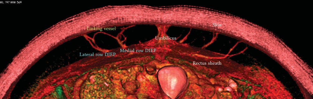
CTA currently has the capability to preoperatively visualise perforator branching networks and inter-perforator zones in-vivo (figures 2 and 3) but requires further investigation.


Indocyanine green angiography
Indocyanine green angiography (ICG) is an intraoperative imaging technique involving the intravenous injection of fluorescent indocyanine green dye and laser or infra-red photography, resulting in an image showing the perfusion of the perforator and its branches.
ICG was originally used in cardiothoracic surgery before its application to microvasculature in the free flap transfer.45–47 The advantage of this real-time perfusion imaging is the ability to dynamically assess flap perfusion and identify viable flap tissue,48 allowing resection and modification of the flap intraoperatively49,50 which may reduce post-operative flap necrosis.46,49,51 ICG angiography can also confirm the integrity and flow through of inter-perforator zones.26,37
ICG’s short half-life allows for multiple evaluations52 and minimal impact on surgical time, though the technique is costly.26,53
As a preoperative perforator imaging technique, ICG angiography has limited application48,49,53 and is unable to show deeper anatomy,37,48,53 rendering it inadequate for flap-planning in fatty tissue.52
More research is required to ascertain parameters of hypo-perfusion, but ICG angiography shows promise in dynamically assessing perforasomes intra-operatively.
DIRT
As a perforasome mapping technique, DIRT can be used preoperatively in flap planning and intraoperatively to assess flap viability.
On a thermogram, the perfusion territory of a perforator is indicated by the ‘re-warming’ areas surrounding the hotspot41 and the rate and pattern of re-warming may provide information on the haemodynamic properties of a perforasome.
Chubb and colleagues42 and Taylor and colleagues54 use DIRT to map both the perforasome and the inter-perforator zone, quantitatively showing that the re-warming of a perforasome fits a logarithmic curve. They hypothesise that inter-perforator zones with rapid re-warming that also resemble this logarithmic curve are more robust linking vessels than those that display slow re-warming and do not fit this curve.42
A disadvantage is DIRT inability to measure perfusion of subcutaneous tissue,39 which may impact rates of postoperative fat necrosis.
Discussion
The angiosomes of the body were detailed and mapped by Taylor and Palmer in 1987,1 providing the anatomical basis of our understanding of vascular territories today. Their studies were undertaken in cadavers, using dye, lead oxide and X-ray imaging. They defined an angiosome as a composite block of tissue supplied by a named source artery and showed true and choke anastomoses (or direct and indirect linking vessels2) between adjacent angiosomes.1 More recently, Taylor further explored these anastomoses with angiosome mapping in animals, using lead oxide and radiographic images in cadavers and fluorescein and ink in-vivo.55 He described choke anastomoses (indirect linking vessels) as reduced calibre vessels, and the most common inter-connection. Less frequently, a true anastomosis (or direct linking vessel) exists between angiosomes, and this linking vessel is of the same calibre as the vessels it joins (Figure 2). These anastomoses control flow between angiosomes and hence flap design should be dictated by the type of linking vessels present.55 Interestingly, choke anastomoses can be converted to true, via hyperplasia, after hyper-perfusion in the setting of flap reconstruction.55 These findings may be applied to perforasomes and have significant implications in perforator flap reconstruction, especially if the discussed imaging techniques can be applied to inter-perforator zones and the assessment of anastomotic calibre.
With a growing number of ways to visualise perforasomes, the condition under which imaging is performed becomes increasingly important. First, in-vivo imaging is subject to various factors that affect vessel behaviour and hence impact the picture of perfused territory produced. Thermal, hormonal and neuronal56 elements can all influence perfusion zones by altering the dilatation and calibre of vessels. Cadaveric imaging, in contrast, is not influenced by these dynamic factors, leading to a different perforasome image than when carried out in-vivo. Similarly, pre-, intra- and post-operative imaging can each lead to slightly different perfusion pictures due to neuronal, hormonal, thermal and pressure differences.
Finally, a note on nomenclature of the perforasome and its imaging. The generally accepted definition of a perforasome, as mentioned in this review, is the territory supplied by a single perforator and its branches, the border being at the inter-perforator zone. Taylor and colleagues summarise that this is the anatomical territory of a perforator, defined by a line drawn through the anastomotic zone, while the clinical territory of a perforator comprises the anatomical territory as well as the adjacently-perfused perforasomes.57
Conclusions
Significant developments in imaging techniques have occurred since the introduction of the perforasome concept nearly a decade ago. These imaging techniques each offer different information on perforasomes and have been investigated in many environments—cadaveric, in-vivo, pre- and intraoperatively. In this review, we have illustrated the evolution of these methods from simple perforator location to advanced three-dimensional imaging and real-time dynamic perfusion imaging.
In plastic and reconstructive surgery, the purpose of imaging the perforasome ultimately lies in the reduction and postoperative complications in perforator flap reconstruction and consequently an improvement in outcome measures such as flap loss and fat necrosis. While further research into newer techniques and their translation into clinical outcomes are required, it is clear that with advances and ongoing innovation, perforasome imaging has the potential to improve patient outcomes in perforator flap surgery.
Disclosure
The authors have no conflicts of interest to disclose.
Funding
The authors received no financial support for the research, authorship, and/or publication of this article.
Revised: February 12, 2018